The horizontal turning center is the turning center where the spindle is placed horizontally. So, some people may ask, "What is the turning center?". Before answering this question, please take a look at the photos below.
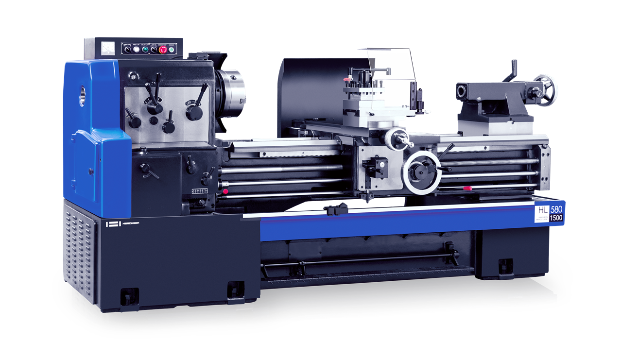
The machine in the above picture is called a lathe, and about 40 years ago, most lathes were like this.
By using the lever on the left to adjust the rotation speed of the spindle, then pull down the red lever in the middle of the right side, and the spindle will rotate. Next, the tool would be moved with rotating the circular handle in the middle of the machine by hand to make the tool contact the workpiece holded on the spindle. The spindle will be stopped by press the foot brake below.
Take a look at the next photo.
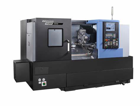
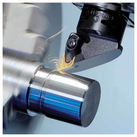
The machine in this photo is the latest appearance of a lathe. It is PUMA GT2100 from DN Solutions. The name of these machines have also been changed. Today it is mostly referred to as a turning center. However, the size and functionality are actually the same as the lathe in the previous photo. That is to say, execute the turning process. While turning the workpiece on the turning spindle on a 2D plane to create the desired geometry. Of course, the final geometry of the workpiece is circular. (Please refer to the following figure)
Let's take a look at the changes.
Firstly, the appearance has changed. There is a cover that isolates the machine from the environment and a safety door is installed to allow for operator or robot to access in to the machine. The turning center is not manually operated by operators, but operated by a computer according to a program. At this point, the space of the machine is completely separated from the outside for safety, so this structure is adopted.
Secondly, as mentioned earlier, the computer is installed on the machine. Computers participate in machine action and status monitoring, as well as signal exchange with othe machines.
At first glance, it seems that there have been significant changes, but the working methods have changed, the processing quality has been leveled up, and work efficiency has been improved, but there has been no fundamental change. But why use the name of the turning center instead of the lathe?
Turning means a cutting process that takes place while the workpiece rotates with fixed tool. Then what does the center mean? The center refers to the comprehensive implementation in one place. Shopping centers, petition centers, and other facilities are also used around us. If you look at DN Solutions PUMA GT2100, the meaning of turning Center is a bit unnatural because the machine is most simple form of turning centers.
In fact, there are other reasons for using the term 'turning center'. Now let's get to know more.
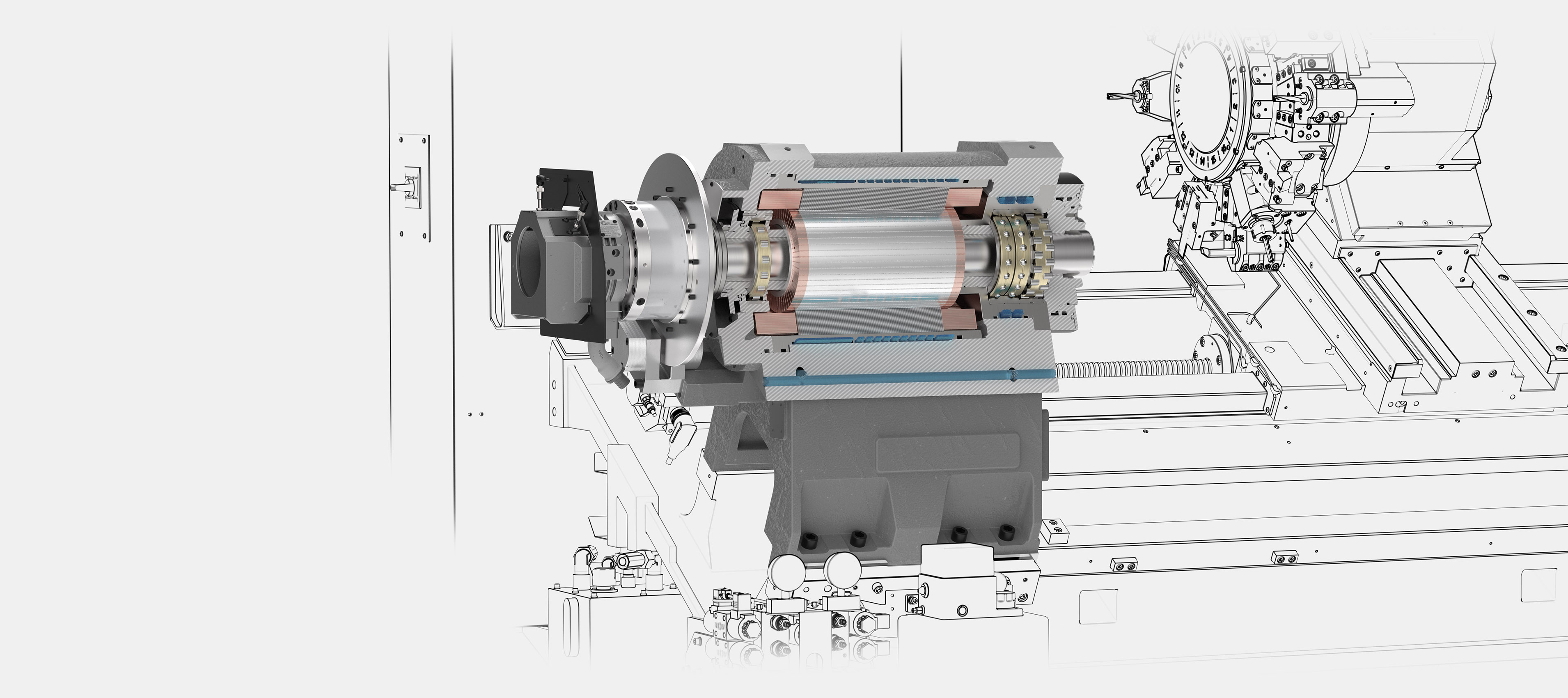
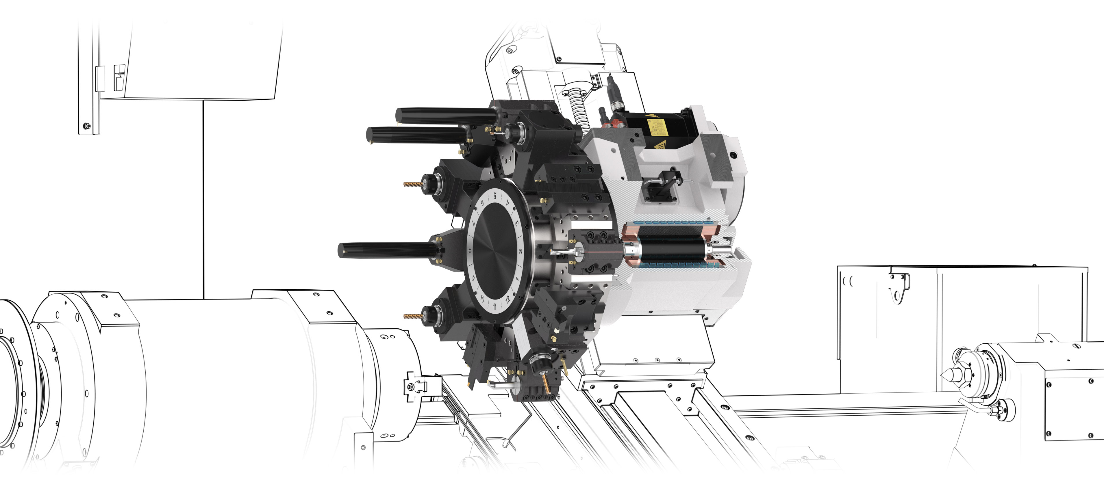
This is the main working spindle of the lathe or turning center. This spindle is called main turning spindle or turning spindle no. 1 also.
The number of available tools is an important factor in the machining process. Each tool post can be mounted from 4 to 24.
Gang is a plate of arranging the required tools in a row. Usually, 4 to 6 tools can be placed. The selection of tools is controlled by the X-axis, so the X-axis usually becomes longer than other types of machines.
Turret is a method of placing the tool on the surface and side of a flat cylindrical shape, and dividing it to select the tool.
The tool holders used for turret usually adopts three methods:
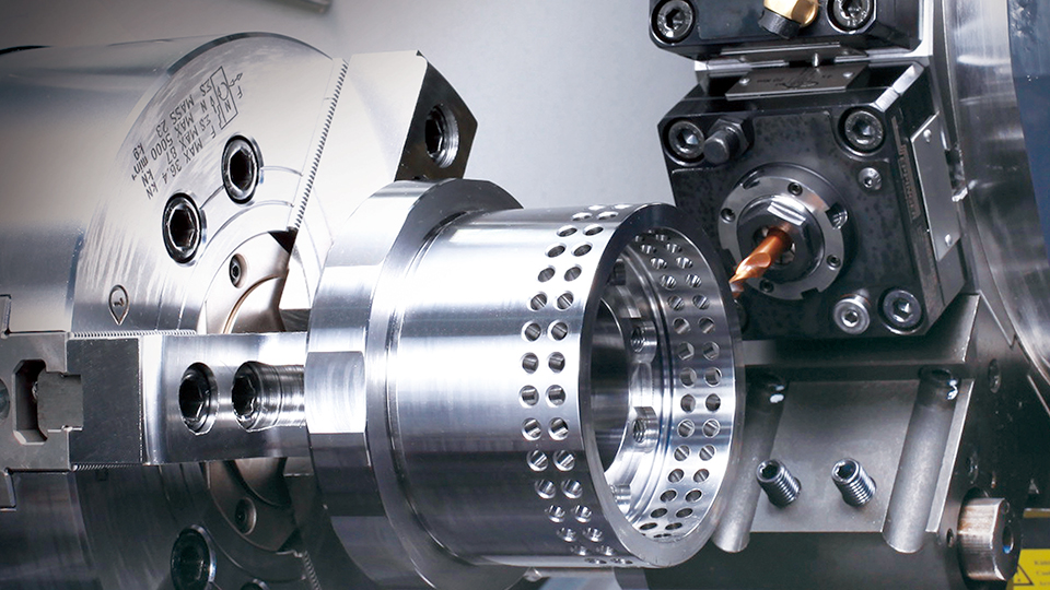
The use of driven tools(or rotating tools, live tools, revolvers) in the turning center not only allows for turning, but also for drilling, tapping, and milling. Some processes in the machining center can also be carried out in the turning center. Rotating motion can also be converted into linear motion, so special machining can also be carried out according to the type of rotating tool.
Also called the counter spindle, pick-off spindle, back spindle, secondary spindle or turning spindle no. 2, this spindle is located to the right of the main spindle and can be identical to or inferior to the main spindle. When the word sub-spindle is used, it typically means that the spindle to the right is inferior to the spindle to the left.
The sub-spindle can be of the same size and capacity as the main spindle, and can also have smaller power, chuck, and barworking diameter. Two spindles face each other, and the sub-spindle can move along the z-axis, and some type of movement may occur between the spindles. In this way, after completing the main spindle process, the workpiece can be moved to the sub-spindle to complete the subsequent process.
As mentioned earlier, the most common axis feed for the sub spindle is the Z-axis. This can support the workpiece of the main spindle or take over the workpiece from the main spindle.
On the sub-spindle, in addition to the Z-axis, it is also possible to move along the X-axis direction in some machines. This can reduce interference with the tool post or adopt synchronous machining.
Usually, the sub spindle or the tail stock exists alone, but some machines have both of them. X axis is used to select them.
The rotating tools mounted on the turret has certain limitations in machining capacity. If the milling spindle is mounted in stead, its performance would be the same as that of the machining center. Most of mill-turns have a milling spindle as standard.
In the past, most of lathes had a flat bed. A flat bed refers to a bed with a horizontal guide ways. Afterwards, with the emergence of the turning center, the slant bed began to be used. The characteristic of an slant bed is that the chip and cutting oil flow downward along the inclined plane, so the processing of the chip and cutting oil is easy. Meanwhile, its another advantage is that operator can access the workpiece more easily. This is a important factor not only in a general usage condition, but also in automation.
Taking small turning centers as an example, although it appears to be a slant bed, there are also machines that have a flat bed. The effect of slant bed can be achieved by slanting Z-axis slide. This type of machine is classified as an slant bed.
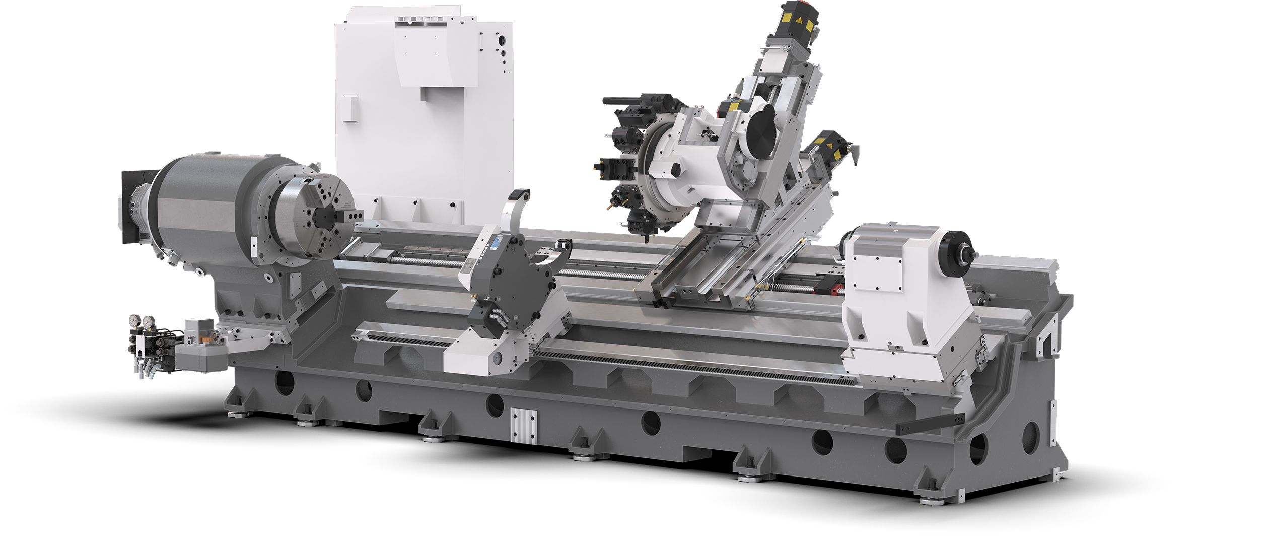
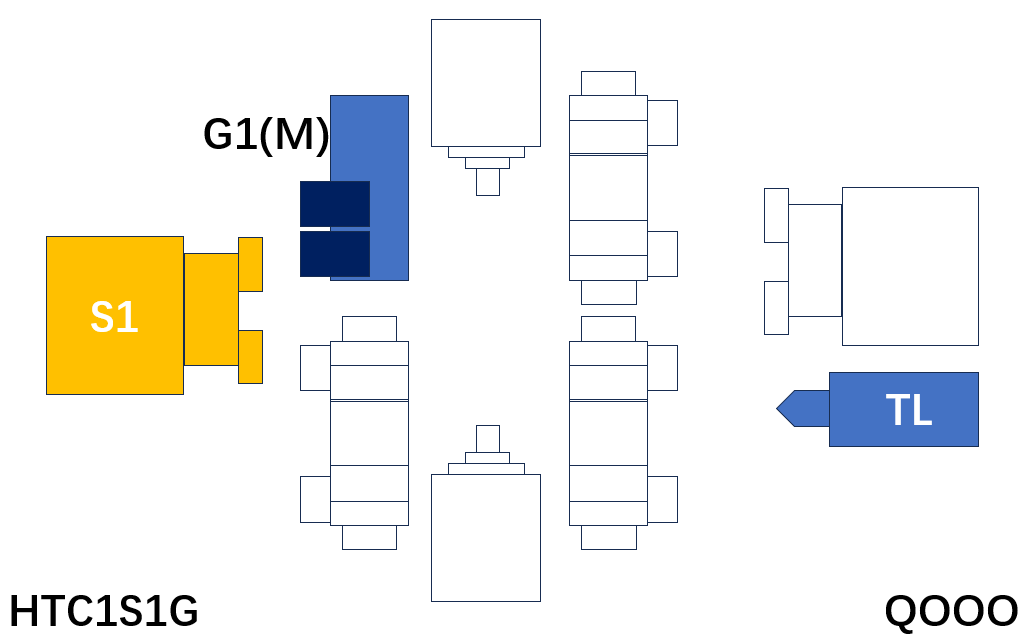
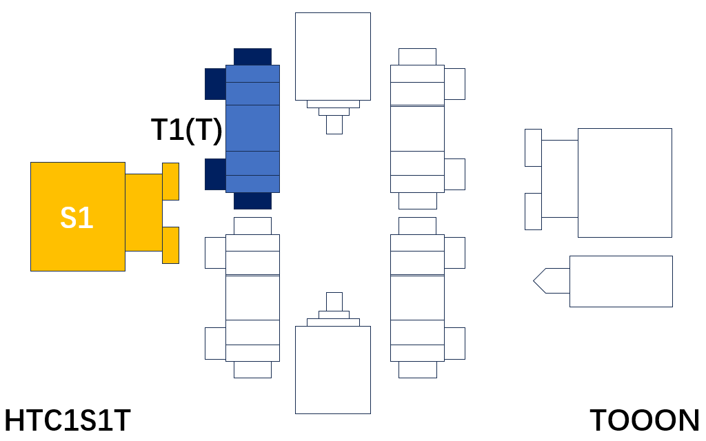
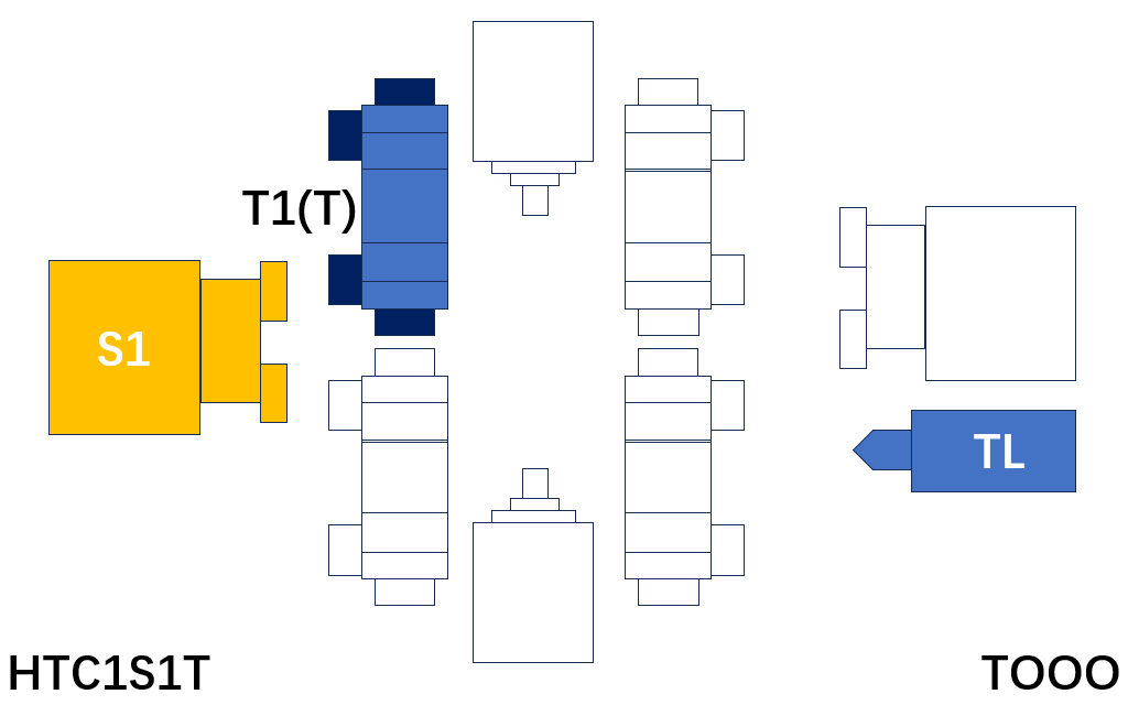
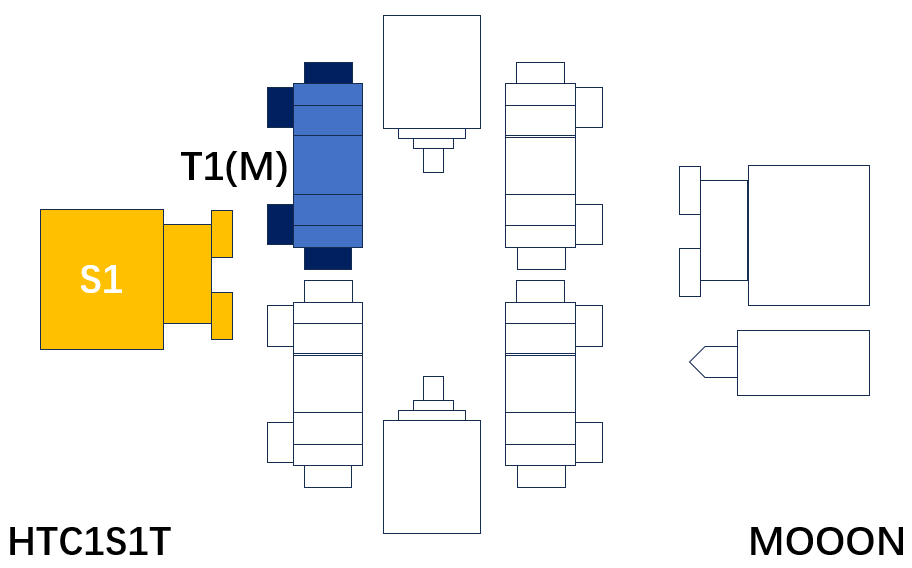
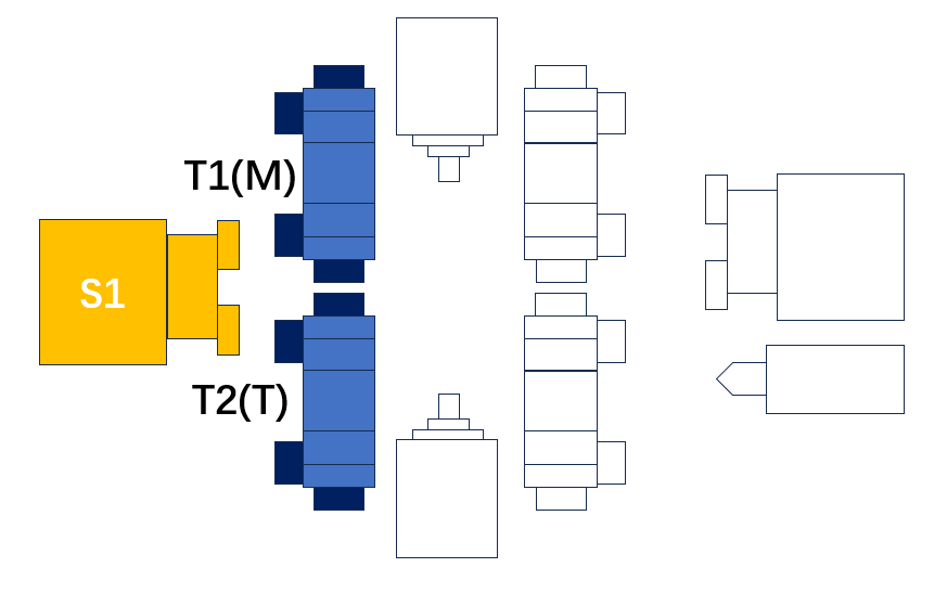
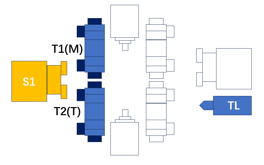
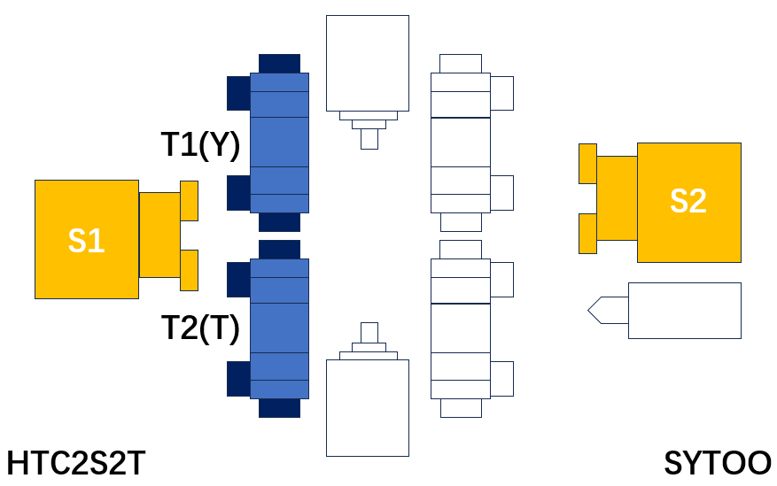
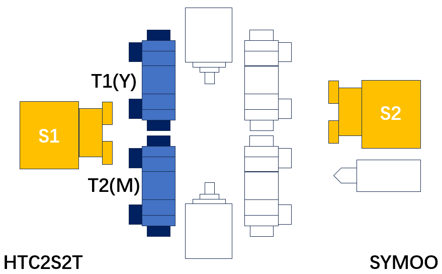
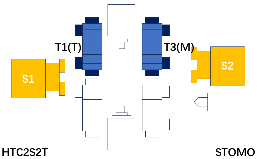
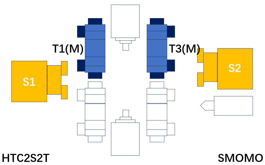
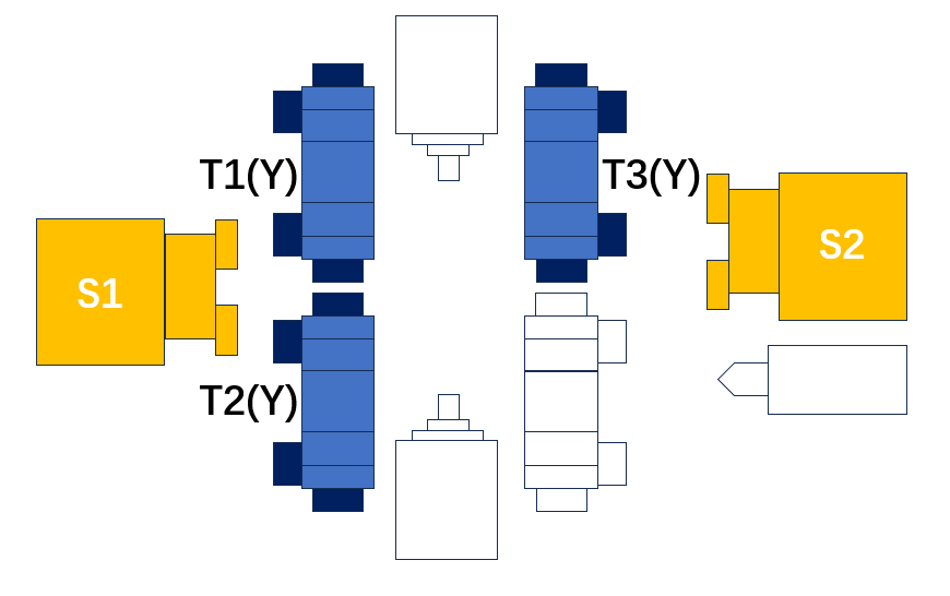
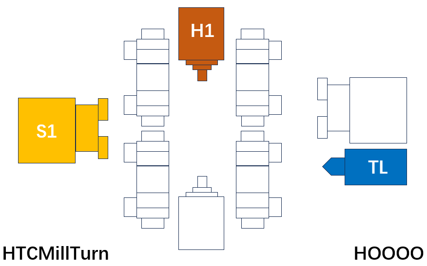
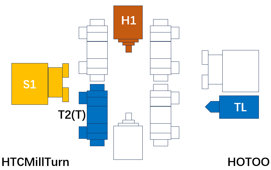
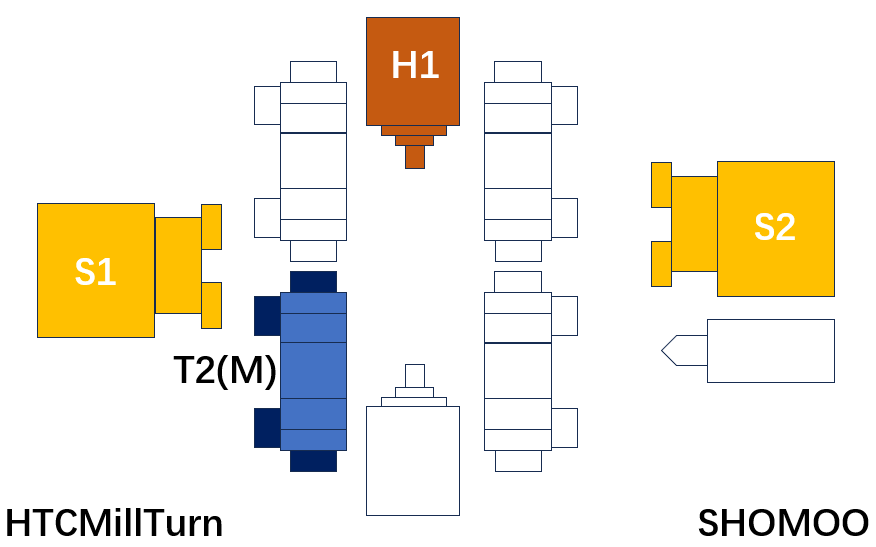
Let's integrate all the above features. Let's take a look at the next picture.
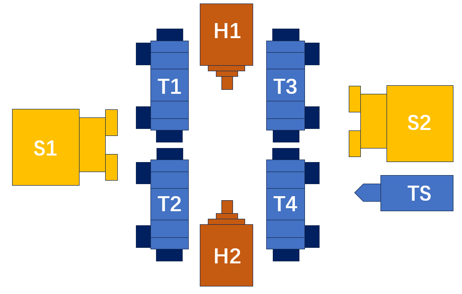
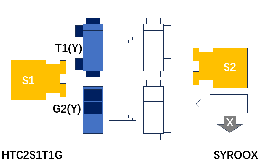
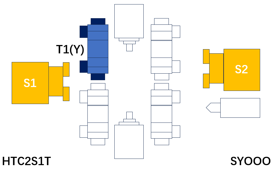
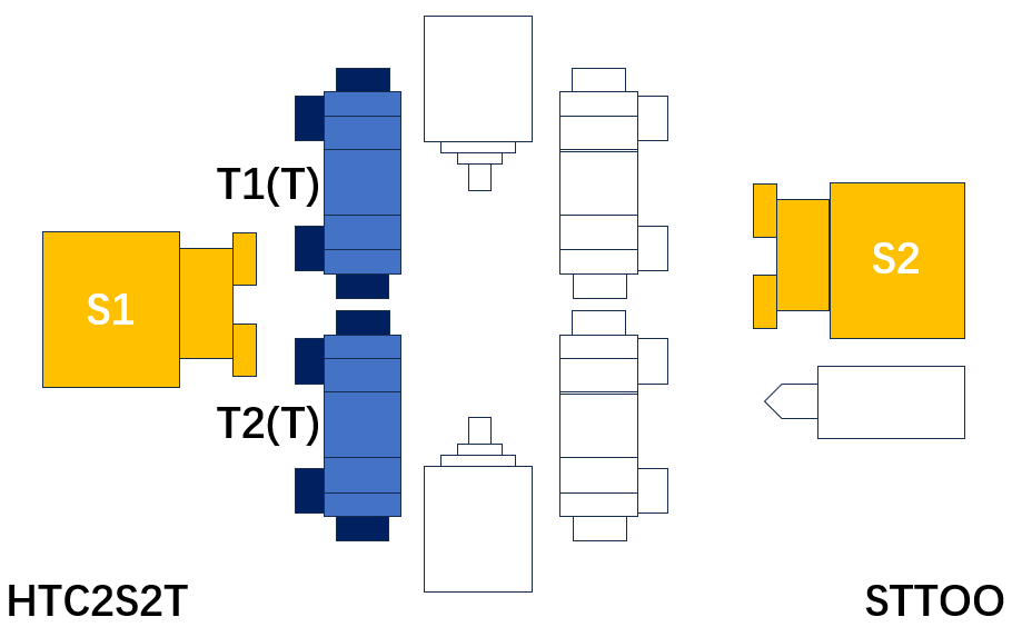
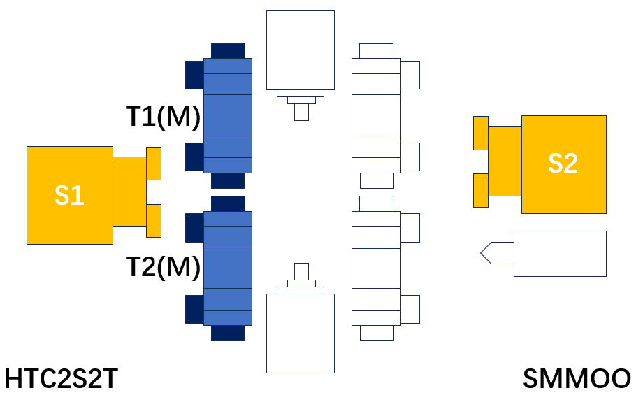
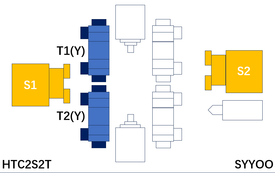
S1: Turning spindle #1 S2: Turning spindle #2 H1: Milling spindle #1 H2: Milling spindle #2 T1: Toolpost #1 T2: Toolpost #2 T3: Toolpost #3 T4: Toolpost #4 TS: Tail stock
This is the conceptual map of the Tening Center. Although it may seem a bit complicated, this is what modern turning centers look like. As long as you understand this concept, you can distinguish most of the machines currently available on the market.
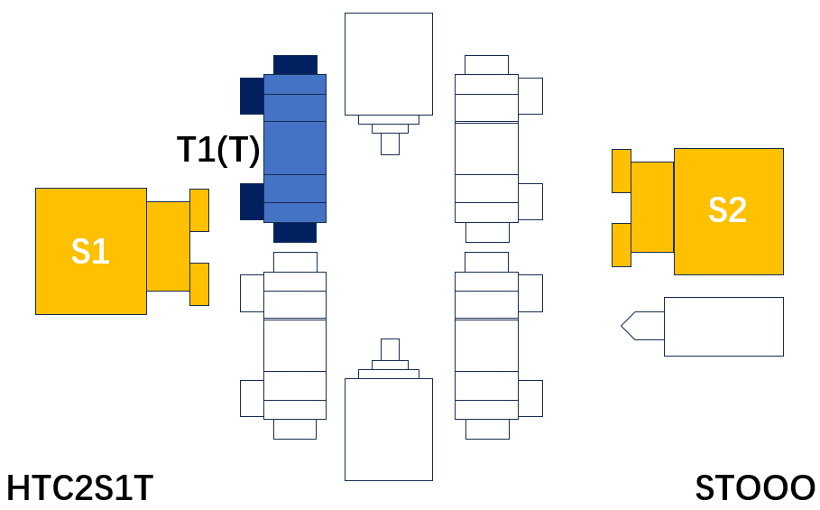
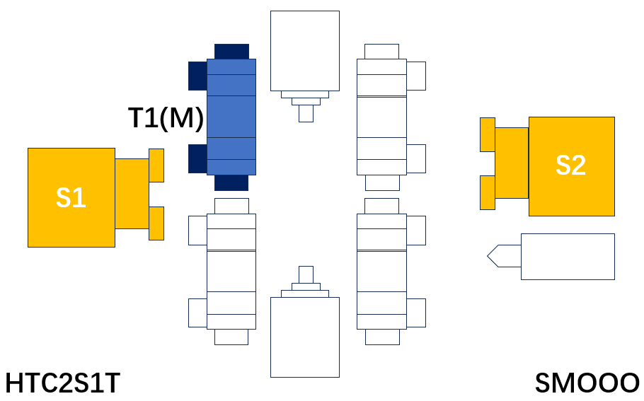
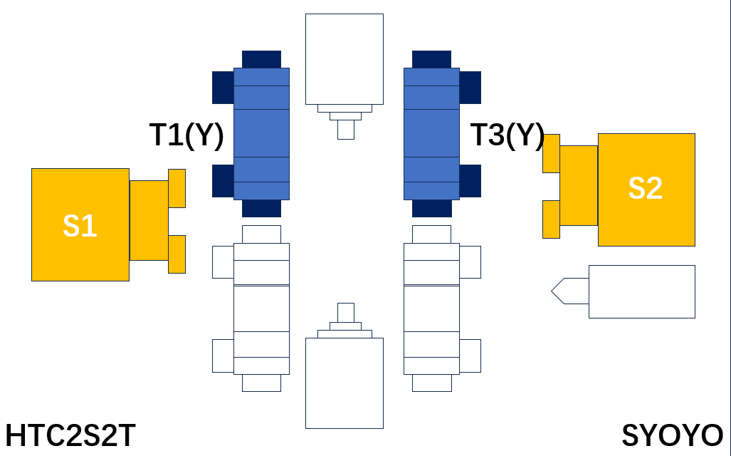
To imporve comprehension of conceptual map, take a example of PUMA GT2100 from DN Solutions. Let's adjust several diagram according to PUMA GT2100.
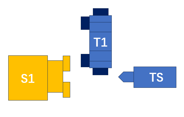
How's it going? Isn't it simple now? In fact, most turning centers can be expressed using conceptual diagrams of turning centers. Of course, there may be some not regular variants.
Shall we wrap up the key points introduced on this page?
1. The turning center is a combination of 2 turning spindles, 2 milling spindles, 4 tool posts, and 1 tail stock.
2. Depending on the combination, the turning center can perform various forms of processing from a 2-axis turning center to a 5-axis machine.
The purpose of the turning center is to ensure the accuracy of the workpiece and improve production efficiency through integrating process. Turning centers would be recommended for efficient production of high value-added workpieces.
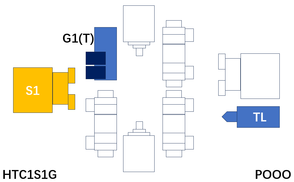
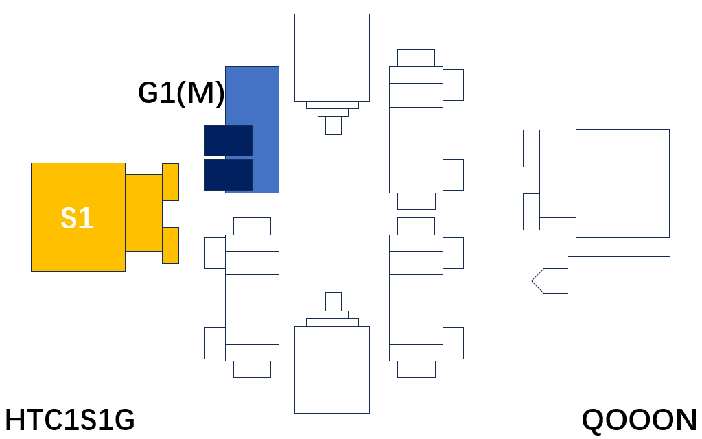
So, now let's take a look at the actual products used on site. The following is the Turning Center search function provided by MTF by type. Click the 'Submit' button to view the product list
TS: Turning Spinde, Gang(T): Gang with Static Tool, Gang(M): Gang with Driven Tool, Gang(Y): Gang with Y-axis and Driven Tool,Turret(T): Turret with Static Tool, Turret(M): Turret with Driven Tool, Turret(Y): Turret with Y-axis and Driven Tool

| No. | 卡盘大小(S1) | 工件长度 | 按钮 |
| 1 | 3 | 所有 | 提交 |
| 2 | 5 | 所有 | 提交 |
| 3 | 6 | 所有 | 提交 |
| 4 | 8 | 所有 | 提交 |
| 5 | 10 | 所有 | 提交 |
| 6 | 所有 | 所有 | 提交 |
| No. | 卡盘大小(S1) | 工件长度 | 按钮 |
| 1 | 6 | 所有 | 提交 |
| 2 | 8 | 所有 | 提交 |
| 3 | 10 | 所有 | 提交 |
| 4 | 所有 | 所有 | 提交 |
| No. | 卡盘大小(S1) | 工件长度 | 按钮 |
| 1 | 所有 | 所有 | 提交 |
| No. | 卡盘大小(S1) | 工件长度 | 按钮 |
| 1 | 所有 | 所有 | 提交 |
| No. | 卡盘大小(S1) | 工件长度 | 按钮 |
| 1 | 所有 | 所有 | 提交 |
| No. | 卡盘大小(S1) | 工件长度 | 按钮 |
| 1 | 所有 | 所有 | 提交 |
| No. | 卡盘大小(S1) | 工件长度 | 按钮 |
| 1 | 6 | 所有 | 提交 |
| 2 | 8 | 所有 | 提交 |
| 3 | 所有 | 所有 | 提交 |
| No. | 卡盘大小(S1) | 工件长度 | 按钮 |
| 1 | 6 | 0~250 | 提交 |
| 2 | 6 | 250~500 | 提交 |
| 3 | 6 | 500~750 | 提交 |
| 4 | 6 | 750~1000 | 提交 |
| 5 | 6 | 1000~1500 | 提交 |
| 6 | 6 | 1500~2000 | 提交 |
| 7 | 6 | 2000~3000 | 提交 |
| 8 | 8 | 0~500 | 提交 |
| 9 | 8 | 500~750 | 提交 |
| 10 | 8 | 750~1000 | 提交 |
| 11 | 8 | 1000~1500 | 提交 |
| 12 | 8 | 1500~2000 | 提交 |
| 13 | 8 | 2000~3000 | 提交 |
| 14 | 10 | 0~500 | 提交 |
| 15 | 10 | 500~750 | 提交 |
| 16 | 10 | 750~1000 | 提交 |
| 17 | 10 | 1000~1500 | 提交 |
| 18 | 10 | 1500~2000 | 提交 |
| 19 | 10 | 2000~3000 | 提交 |
| 20 | 12 | 0~500 | 提交 |
| 21 | 12 | 500~750 | 提交 |
| 22 | 12 | 750~1000 | 提交 |
| 23 | 12 | 1000~1500 | 提交 |
| 24 | 12 | 1500~2000 | 提交 |
| 25 | 12 | 2000~3000 | 提交 |
| 26 | 12 | 3000~4000 | 提交 |
| 27 | 12 | 4000~5000 | 提交 |
| 28 | 15 | 0~500 | 提交 |
| 29 | 15 | 500~1000 | 提交 |
| 30 | 15 | 1000~1500 | 提交 |
| 31 | 15 | 1500~2000 | 提交 |
| 32 | 15 | 2000~3000 | 提交 |
| 33 | 15 | 3000~4000 | 提交 |
| 34 | 15 | 4000~5000 | 提交 |
| 35 | 15 | 5000~6000 | 提交 |
| 36 | 15 | 6000~7000 | 提交 |
| 37 | 18 | 1000~1500 | 提交 |
| 38 | 18 | 1500~2000 | 提交 |
| 39 | 18 | 2000~3000 | 提交 |
| 40 | 18 | 3000~4000 | 提交 |
| 41 | 18 | 4000~5000 | 提交 |
| 42 | 18 | 5000~6000 | 提交 |
| 43 | 18 | 6000~7000 | 提交 |
| 44 | 21 | 1000~2000 | 提交 |
| 45 | 21 | 2000~3000 | 提交 |
| 46 | 21 | 3000~4000 | 提交 |
| 47 | 21 | 4000~5000 | 提交 |
| 48 | 21 | 5000~6000 | 提交 |
| 49 | 21 | 6000~7000 | 提交 |
| 50 | 24 | 1000~2000 | 提交 |
| 51 | 24 | 2000~3000 | 提交 |
| 52 | 24 | 3000~4000 | 提交 |
| 53 | 24 | 4000~5000 | 提交 |
| 54 | 24 | 5000~6000 | 提交 |
| 55 | 24 | 6000~7000 | 提交 |
| 56 | 32 | 1000~2000 | 提交 |
| 57 | 32 | 2000~3000 | 提交 |
| 58 | 32 | 3000~4000 | 提交 |
| 59 | 32 | 4000~5000 | 提交 |
| 60 | 32 | 5000~6000 | 提交 |
| 61 | 32 | 6000~7000 | 提交 |
| No. | 卡盘大小(S1) | 工件长度 | 按钮 |
| 1 | 所有 | 所有 | 提交 |

| No. | 卡盘大小(S1) | 工件长度 | 按钮 |
| 1 | 6 | 0~250 | 提交 |
| 2 | 6 | 250~500 | 提交 |
| 3 | 6 | 500~1000 | 提交 |
| 4 | 6 | 1000~1500 | 提交 |
| 5 | 6 | 1500~2000 | 提交 |
| 6 | 6 | 2000~3000 | 提交 |
| 7 | 8 | 0~500 | 提交 |
| 8 | 8 | 500~1000 | 提交 |
| 9 | 8 | 1000~2000 | 提交 |
| 10 | 8 | 2000~3000 | 提交 |
| 11 | 10 | 0~500 | 提交 |
| 12 | 10 | 500~1000 | 提交 |
| 13 | 10 | 1000~2000 | 提交 |
| 14 | 10 | 2000~3000 | 提交 |
| 15 | 12 | 0~1000 | 提交 |
| 16 | 12 | 1000~2000 | 提交 |
| 17 | 12 | 2000~3000 | 提交 |
| 18 | 12 | 3000~4000 | 提交 |
| 19 | 12 | 4000~5000 | 提交 |
| 20 | 15 | 0~1000 | 提交 |
| 21 | 15 | 1000~2000 | 提交 |
| 22 | 15 | 2000~3000 | 提交 |
| 23 | 15 | 3000~4000 | 提交 |
| 24 | 15 | 4000~5000 | 提交 |
| 25 | 15 | 5000~6000 | 提交 |
| 26 | 15 | 6000~7000 | 提交 |
| 27 | 18 | 1000~2000 | 提交 |
| 28 | 18 | 2000~3000 | 提交 |
| 29 | 18 | 3000~4000 | 提交 |
| 30 | 18 | 4000~5000 | 提交 |
| 31 | 18 | 5000~6000 | 提交 |
| 32 | 18 | 6000~7000 | 提交 |
| 33 | 21 | 1000~2000 | 提交 |
| 34 | 21 | 2000~3000 | 提交 |
| 35 | 21 | 3000~4000 | 提交 |
| 36 | 21 | 4000~5000 | 提交 |
| 37 | 21 | 5000~6000 | 提交 |
| 38 | 21 | 6000~7000 | 提交 |
| 39 | 24 | 1000~2000 | 提交 |
| 40 | 24 | 2000~3000 | 提交 |
| 41 | 24 | 3000~4000 | 提交 |
| 42 | 24 | 4000~5000 | 提交 |
| 43 | 24 | 5000~6000 | 提交 |
| 44 | 24 | 6000~7000 | 提交 |
| 45 | 32 | 1000~2000 | 提交 |
| 46 | 32 | 2000~3000 | 提交 |
| 47 | 32 | 3000~4000 | 提交 |
| 48 | 32 | 4000~5000 | 提交 |
| 49 | 32 | 5000~6000 | 提交 |
| 50 | 32 | 6000~7000 | 提交 |
| No. | 卡盘大小(S1) | 工件长度 | 按钮 |
| 1 | 所有 | 所有 | 提交 |
| No. | 卡盘大小(S1) | 工件长度 | 按钮 |
| 1 | 6 | 0~250 | 提交 |
| 2 | 6 | 250~500 | 提交 |
| 3 | 6 | 500~1000 | 提交 |
| 4 | 6 | 1000~1500 | 提交 |
| 5 | 6 | 1500~2000 | 提交 |
| 6 | 6 | 2000~3000 | 提交 |
| 7 | 8 | 0~500 | 提交 |
| 8 | 8 | 500~1000 | 提交 |
| 9 | 8 | 1000~2000 | 提交 |
| 10 | 8 | 2000~3000 | 提交 |
| 11 | 10 | 0~500 | 提交 |
| 12 | 10 | 500~1000 | 提交 |
| 13 | 10 | 1000~2000 | 提交 |
| 14 | 10 | 2000~3000 | 提交 |
| 15 | 12 | 0~1000 | 提交 |
| 16 | 12 | 1000~2000 | 提交 |
| 17 | 12 | 2000~3000 | 提交 |
| 18 | 12 | 3000~4000 | 提交 |
| 19 | 12 | 4000~5000 | 提交 |
| 20 | 15 | 0~1000 | 提交 |
| 21 | 15 | 1000~2000 | 提交 |
| 22 | 15 | 2000~3000 | 提交 |
| 23 | 15 | 3000~4000 | 提交 |
| 24 | 15 | 4000~5000 | 提交 |
| 25 | 15 | 5000~6000 | 提交 |
| 26 | 15 | 6000~7000 | 提交 |
| 27 | 18 | 1000~2000 | 提交 |
| 28 | 18 | 2000~3000 | 提交 |
| 29 | 18 | 3000~4000 | 提交 |
| 30 | 18 | 4000~5000 | 提交 |
| 31 | 18 | 5000~6000 | 提交 |
| 32 | 18 | 6000~7000 | 提交 |
| 33 | 21 | 1000~2000 | 提交 |
| 34 | 21 | 2000~3000 | 提交 |
| 35 | 21 | 3000~4000 | 提交 |
| 36 | 21 | 4000~5000 | 提交 |
| 37 | 21 | 5000~6000 | 提交 |
| 38 | 21 | 6000~7000 | 提交 |
| 39 | 24 | 1000~2000 | 提交 |
| 40 | 24 | 2000~3000 | 提交 |
| 41 | 24 | 3000~4000 | 提交 |
| 42 | 24 | 4000~5000 | 提交 |
| 43 | 24 | 5000~6000 | 提交 |
| 44 | 24 | 6000~7000 | 提交 |
| 45 | 32 | 1000~2000 | 提交 |
| 46 | 32 | 2000~3000 | 提交 |
| 47 | 32 | 3000~4000 | 提交 |
| 48 | 32 | 4000~5000 | 提交 |
| 49 | 32 | 5000~6000 | 提交 |
| 50 | 32 | 6000~7000 | 提交 |
| No. | 卡盘大小(S1) | 工件长度 | 按钮 |
| No. | 卡盘大小(S1) | 工件长度 | 按钮 |
| No. | 卡盘大小(S1) | 工件长度 | 按钮 |
| No. | 卡盘大小(S1) | 工件长度 | 按钮 |
| No. | 卡盘大小(S1) | 工件长度 | 按钮 |
| No. | 卡盘大小(S1) | 工件长度 | 按钮 |
| No. | 卡盘大小(S1) | 工件长度 | 按钮 |
| No. | 卡盘大小(S1) | 工件长度 | 按钮 |
| No. | 卡盘大小(S1) | 工件长度 | 按钮 |
| No. | 卡盘大小(S1) | 工件长度 | 按钮 |
| No. | 卡盘大小(S1) | 工件长度 | 按钮 |
| No. | 卡盘大小(S1) | 工件长度 | 按钮 |
| No. | 卡盘大小(S1) | 工件长度 | 按钮 |
| No. | 卡盘大小(S1) | 工件长度 | 按钮 |
| 1 | 所有 | 所有 | 提交 |
| No. | 卡盘大小(S1) | 工件长度 | 按钮 |
| 1 | 所有 | 所有 | 提交 |
| No. | 卡盘大小(S1) | 工件长度 | 按钮 |
| No. | 卡盘大小(S1) | 工件长度 | 按钮 |
| 1 | 6 | 所有 | 提交 |
| 2 | 8 | 所有 | 提交 |
| 3 | 10 | 所有 | 提交 |
| 4 | 所有 | 所有 | 提交 |
| No. | 卡盘大小(S1) | 工件长度 | 按钮 |
| 1 | 所有 | 所有 | 提交 |
| No. | 卡盘大小(S1) | 工件长度 | 按钮 |
| 1 | 所有 | 所有 | 提交 |
| No. | 卡盘大小(S1) | 工件长度 | 按钮 |
| No. | 卡盘大小(S1) | 工件长度 | 按钮 |
| 1 | 6 | 所有 | 提交 |
| 2 | 8 | 所有 | 提交 |
| 3 | 10 | 所有 | 提交 |
| 4 | 所有 | 所有 | 提交 |
| No. | 卡盘大小(S1) | 工件长度 | 按钮 |
| 1 | 6 | 所有 | 提交 |
| 2 | 8 | 所有 | 提交 |
| 3 | 10 | 所有 | 提交 |
| 4 | 所有 | 所有 | 提交 |

| No. | 卡盘大小(S1) | 工件长度 | 按钮 |
| 1 | 5 | 所有 | 提交 |
| 2 | 6 | 所有 | 提交 |
| 3 | 所有 | 所有 | 提交 |
| No. | 卡盘大小(S1) | 工件长度 | 按钮 |
| 1 | 5 | 所有 | 提交 |
| 2 | 6 | 所有 | 提交 |
| 3 | 所有 | 所有 | 提交 |
| No. | 卡盘大小(S1) | 工件长度 | 按钮 |
| 1 | 所有 | 所有 | 提交 |

| No. | 卡盘大小(S1) | 工件长度 | 按钮 |
| 1 | 所有 | 所有 | 提交 |
| No. | 卡盘大小(S1) | 工件长度 | 按钮 |
| 1 | 所有 | 所有 | 提交 |
| No. | 卡盘大小(S1) | 工件长度 | 按钮 |
| No. | 卡盘大小(S1) | 工件长度 | 按钮 |
| No. | 卡盘大小(S1) | 工件长度 | 按钮 |
| No. | 卡盘大小(S1) | 工件长度 | 按钮 |
| No. | 卡盘大小(S1) | 工件长度 | 按钮 |
| No. | 卡盘大小(S1) | 工件长度 | 按钮 |
| No. | 卡盘大小(S1) | 工件长度 | 按钮 |
| No. | 卡盘大小(S1) | 工件长度 | 按钮 |
| No. | 卡盘大小(S1) | 工件长度 | 按钮 |
| No. | 卡盘大小(S1) | 工件长度 | 按钮 |
| No. | 床身上回转直径 | 工件长度 | 按钮 |
| 1 | 0~500 | 0~1000 | 提交 |
| 2 | 0~500 | 1000~2000 | 提交 |
| 3 | 0~500 | 2000~3000 | 提交 |
| 4 | 500~1000 | 0~1000 | 提交 |
| 5 | 500~1000 | 1000~2000 | 提交 |
| 6 | 500~1000 | 2000~3000 | 提交 |
| 7 | 500~1000 | 3000~4000 | 提交 |
| 8 | 500~1000 | 4000~5000 | 提交 |
| 9 | 500~1000 | 5000~6000 | 提交 |
| 10 | 500~1000 | 6000~7000 | 提交 |
| 11 | 500~1000 | 7000~8000 | 提交 |
| 12 | 1000~1500 | 0~1000 | 提交 |
| 13 | 1000~1500 | 1000~2000 | 提交 |
| 14 | 1000~1500 | 2000~3000 | 提交 |
| 15 | 1000~1500 | 3000~4000 | 提交 |
| 16 | 1000~1500 | 4000~5000 | 提交 |
| 17 | 1000~1500 | 5000~6000 | 提交 |
| 18 | 1000~1500 | 6000~7000 | 提交 |
| 19 | 1000~1500 | 7000~8000 | 提交 |
| 20 | 1000~1500 | 8000~9000 | 提交 |
| 21 | 1000~1500 | 9000~10000 | 提交 |
| 22 | 1000~1500 | 10000~12000 | 提交 |
| 23 | 1000~1500 | 12000~14000 | 提交 |
| 24 | 1000~1500 | 14000~16000 | 提交 |
| 25 | 1500~1750 | 0~1000 | 提交 |
| 26 | 1500~1750 | 1000~2000 | 提交 |
| 27 | 1500~1750 | 2000~3000 | 提交 |
| 28 | 1500~1750 | 3000~4000 | 提交 |
| 29 | 1500~1750 | 4000~5000 | 提交 |
| 30 | 1500~1750 | 5000~6000 | 提交 |
| 31 | 1500~1750 | 6000~7000 | 提交 |
| 32 | 1500~1750 | 7000~8000 | 提交 |
| 33 | 1500~1750 | 8000~9000 | 提交 |
| 34 | 1500~1750 | 9000~10000 | 提交 |
| 35 | 1500~1750 | 10000~12000 | 提交 |
| 36 | 1750~2000 | 0~1000 | 提交 |
| 37 | 1750~2000 | 1000~2000 | 提交 |
| 38 | 1750~2000 | 2000~3000 | 提交 |
| 39 | 1750~2000 | 3000~4000 | 提交 |
| 40 | 1750~2000 | 4000~5000 | 提交 |
| 41 | 1750~2000 | 5000~6000 | 提交 |
| 42 | 1750~2000 | 6000~7000 | 提交 |
| 43 | 1750~2000 | 7000~8000 | 提交 |
| 44 | 1750~2000 | 8000~9000 | 提交 |
| 45 | 1750~2000 | 9000~10000 | 提交 |
| 46 | 1750~2000 | 10000~12000 | 提交 |
| No. | 卡盘大小(S1) | 工件长度 | 按钮 |
| 1 | 8 | 0~1000 | 提交 |
| 2 | 8 | 1000~1500 | 提交 |
| 3 | 8 | 1500~2000 | 提交 |
| 4 | 10 | 0~1000 | 提交 |
| 5 | 10 | 1000~1500 | 提交 |
| 6 | 10 | 1500~2000 | 提交 |
| No. | 卡盘大小(S1) | 工件长度 | 按钮 |
| 1 | 8 | 0~1000 | 提交 |
| 2 | 8 | 1000~1500 | 提交 |
| 3 | 8 | 1500~2000 | 提交 |
| 4 | 10 | 0~1000 | 提交 |
| 5 | 10 | 1000~1500 | 提交 |
| 6 | 10 | 1500~2000 | 提交 |

| No. | 卡盘大小(S1) | 工件长度 | 按钮 |
| 1 | 8 | 0~1000 | 提交 |
| 2 | 8 | 1000~1500 | 提交 |
| 3 | 8 | 1500~2000 | 提交 |
| 4 | 10 | 0~1000 | 提交 |
| 5 | 10 | 1000~1500 | 提交 |
| 6 | 10 | 1500~2000 | 提交 |
| No. | 卡盘大小(S1) | 工件长度 | 按钮 |
| 1 | 8 | 0~1000 | 提交 |
| 2 | 8 | 1000~1500 | 提交 |
| 3 | 8 | 1500~2000 | 提交 |
| 4 | 10 | 0~1000 | 提交 |
| 5 | 10 | 1000~1500 | 提交 |
| 6 | 10 | 1500~2000 | 提交 |